![T_\mathrm{C} \approx T_{\mathrm{n}} + c \left( - 1 + \sqrt[\leftroot{-2}\uproot{-16}\displaystyle{3}]{1 + a \left( - 1 + \displaystyle\frac{1}{1 + b \ln\left(\displaystyle\frac{R_T}{R_\mathrm{n}\right)}\right)}}\right)](eqn-ntc-approx-cab-y18.png)
The characteristics of NTC thermistors (Negative Temperature Coefficient thermistors) for temperature measurement are generally expressed by their resistance value at 25 °C (R25) and the so-called B constant. However, when using the approximation formula based on the B constant, the error increases as the temperature deviates from 25 °C. By using a three-coefficient approximation formula instead, it is possible to approximate within, for example, an error of ±0.2 °C across the entire temperature range relative to the median resistance value.
For commercially available NTC thermistors, the so-called B constant is listed in datasheets as a characteristic value for approximation formulas. For example, in the catalog specifications for Murata Manufacturingfs high-precision NTC thermistor NCP15XH103D03RC (size: 1.0 × 0.5 mm), the values are given as:
R25 = 10 kΩ±1%Approximation Formula for NTC Thermistors Using the B Constant
B(25/50°C) = 3380±0.7%
B(25/85°C)(typical value) = 3434
… (1)
where,
B : Device specific oefficient [K]
TC : Chip temperature [°C]
Tn : Nominal temperature [°C]
Rn : Nominal resistance at Tn [Ω]
RT : Resistance at TC [Ω]
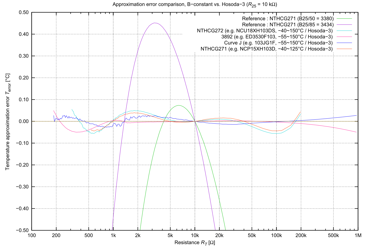
When using an approximation with only a single B constant, significant errors can occur outside the temperature range for which the constant was determined. Additionally, there is a trade-off between error and temperature range\widening the approximation temperature range increases the error. See Fig.1(a) Reference for details.
The exponential approximation using only the B constant cannot accurately approximate the nonlinear temperature characteristics of an NTC thermistor over the entire operating temperature range. However, by noting that the error follows a cubic function pattern, we applied a correction using a Puiseux series-type approximation, as shown in Equation (2) (hereafter referred to as Hosoda-3). This correction enables a more accurate approximation over a wide temperature range, such as -40 to +125 °C. See Fig.1
Approximation Formula for NTC Thermistors Using Three Coefficients (Hosoda-3)
… (2)
where,
a : Device specific coefficient
b : Device specific coefficient
c : Device specific coefficient [K]
TC : Chip temperature [°C]
Tn : Nominal temperature [°C]
Rn : Nominal resistance at Tn [Ω]
RT : Resistance at TC [Ω]
fig.1(a) : Approximation Error Relative to the Median of the NTC Thermistor (R25 = 10 kΩ)
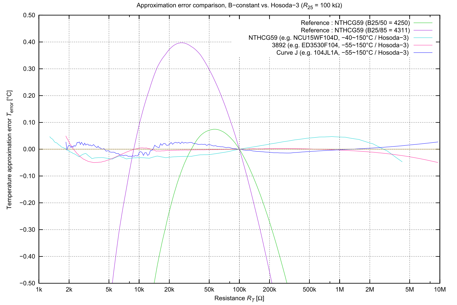
Fig.1(b) Approximation Error Relative to the Median of the NTC Thermistor (R25 = 100 kΩ)Examples of actual coefficients (Hosoda-3)
The component-dependent coefficients a, b, and c in the three-coefficient approximation formula were determined using a computer program to minimize the absolute error within the specified temperature range relative to the median value of each component.
For example, for the previously mentioned NCP15XH103D03RC (Murata), the following coefficients were used:a = 0.37486With these values, the approximation error across the entire -40 °C to +125 °C range was within ±0.044°C.
b = 0.0850436
c = 0.000398951
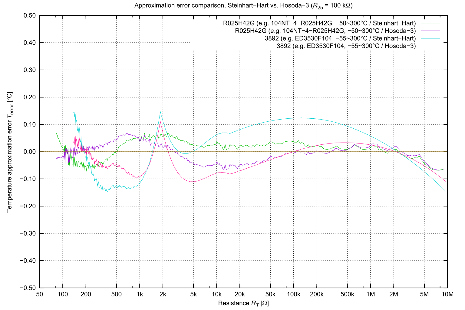
Additionally, for the high-temperature-compatible 104NT-4-R025H42G (Semitec), the following coefficients were used:
a = 0.549425With these values, the approximation error across the entire -50 °C to +300 °C range was within ±0.068 °C. See Fig.2(b)
b = 0.0758081
c = 0.000651657
NTC Thermistor Approximation Formula Using Three Coefficients (Steinhart-Hart)
Another well-known approximation using three coefficients is the Steinhart-Hart equation, shown in Equation (3).
… (3)
where,
A : Device specific coefficient
B : Device specific coefficient
C : Device specific coefficient [K]
T : Chip temperature [°K]
R : Resistance [Ω]
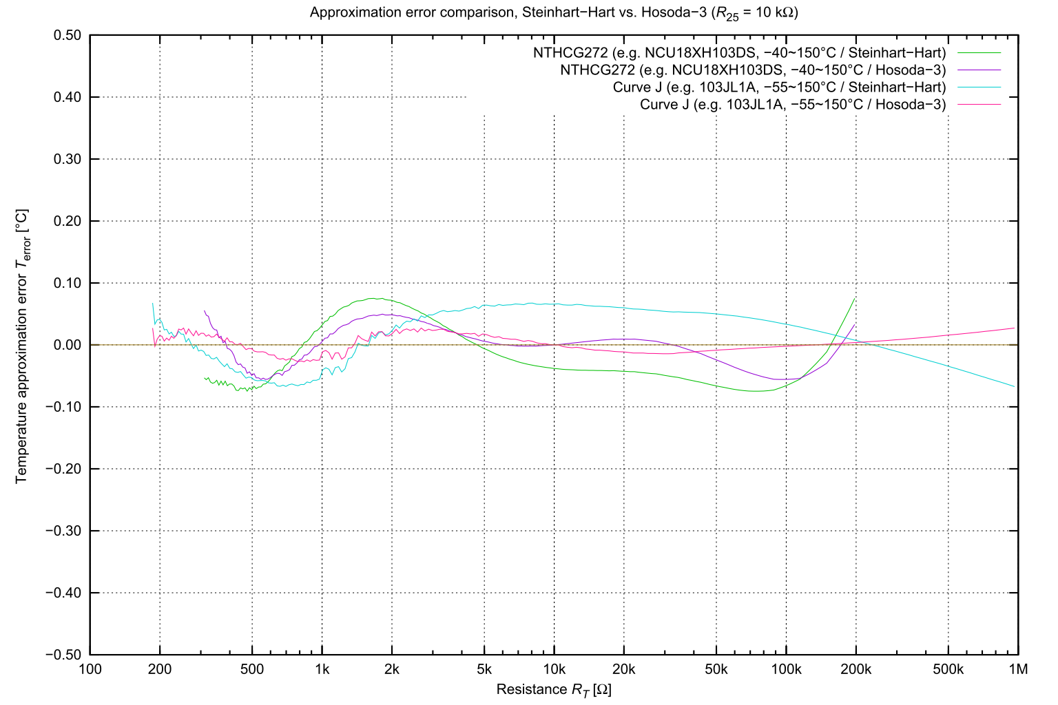
Fig.2(a) Comparison of Steinhart-Hart and Hosoda-3 approximations (R25 = 10 kΩ)
Fig.2(b) Comparison of Steinhart-Hart and Hosoda-3 approximations (R25 = 100 kΩ)The Hosoda-3 approximation ensures that the approximated resistance value matches the rated resistance at the rated temperature, resulting in lower errors around the rated temperature. While differences may exist depending on the temperature range and the thermistor characteristics, the overall error tends to be smaller compared to the Steinhart-Hart approximation, which optimizes its coefficients to minimize the maximum error over the thermistorfs operating temperature range.
By using the Hosoda-3 three-coefficient approximation formula for NTC thermistors described above, we achieved an approximation error within ±0.05 °C over a temperature range of -40 °C to +150 °C for many widely used NTC thermistors from 2010 to 2025. For glass-encapsulated thermistors designed for wide temperature ranges, the approximation error remained within ±0.07 °C over a -50 °C to +300 °C range. Furthermore, for the previously mentioned high-precision thermistors, the temperature could be accurately determined from resistance values with an approximation error within ±0.044 °C across the entire temperature range, without the need for table lookups or interpolation of resistance-temperature characteristics. This capability is expected to contribute to the advancement of devices that require precise temperature measurement.
For coefficients of other NTC thermistors,
Download ntc2tc.js — javascript source code
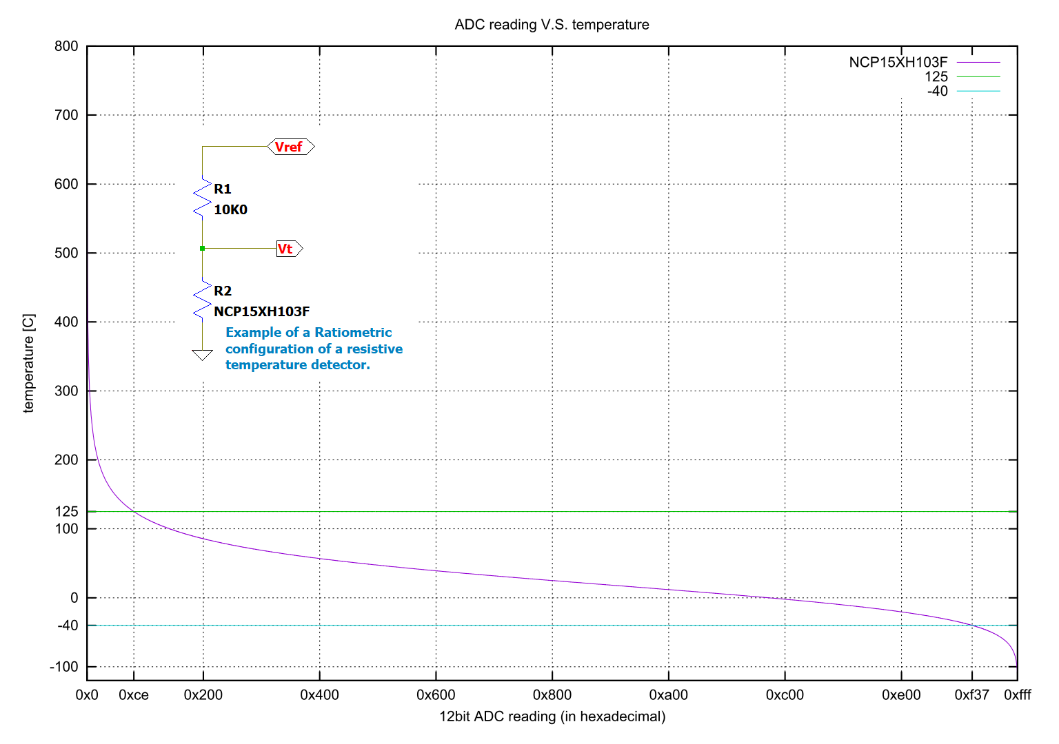
When measuring temperature with an NTC thermistor, instead of directly measuring its resistance, the thermistor and a fixed resistor can be used to divide a reference voltage. The thermistor's value is then measured as a voltage ratio (ratio-metric operation). This method eliminates the influence of the absolute accuracy of the reference voltage. If the fixed resistor is chosen to have the same resistance as the thermistor at 25 °C, the resulting approximation follows a logarithmic rational approximation centered around 25 °C, effectively linearizing the response around this point. For example, in the case of the NCP15XH103F, the measurement range from -25 °C to 85 °C fits within approximately 3/4 of the full-scale range. Conversely, if the thermistor experiences an open circuit or short circuit, it can be detected as an abnormal condition.
Fig.2: Temperature vs. 12-bit ADC Readout for Ratio-Metric NTC Thermistor Configuration (Murata, NCP15XH103F)
- NCP15XH103D03RC Resistance-Temperature Characteristics Table — Murata Manufacturing Thermistor (Temperature Sensor)
- NCU18XH103DS Resistance-Temperature Characteristics Table — Murata Manufacturing Thermistor (Temperature Sensor)
- Takayuki Hosoda, "My Parts Box [8]: High-Precision NTC Thermistor NCP15XH103F03RC," Transistor Technology, July 2012, p.222, CQ Publishing
- NTC Discrete Sensors — Littelfuse Standard Precision Interchangeable Thermistors
- ED3530F103 Resistance vs. Temperature Table — EI Sensor technologies DO-35 Glass Encapsulated Thermistors
January 19, 2022 \ Additional content added
April 5, 2023 \ Additional content added
March 6, 2025 \ Updated Fig.1 and ntc2tc.js
March 16, 2025 \ Additions and corrections and update ntc2tc.js

![[Mail]](/~lyuka/images/mail.gif)


 © 2000 Takayuki HOSODA.