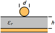
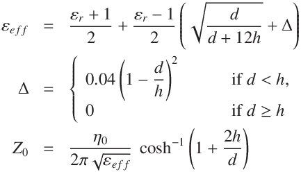
This calculator uses an approximate model that applies microstrip-based formulas to a round conductor. As a result,
the effective relative permittivity may be slightly overestimated.
The error may increase when the conductor diameter is large relative to the substrate thickness (e.g., d/h ≥ 0.4).
If the wire has an insulating coating,
the electric field distribution changes significantly and the model may no longer be valid.
For accurate impedance or effective permittivity values, measurement data or full electromagnetic simulation is recommended.
η0: characteristic impedance of vacuum of free space
376.730313668(57) Ω (CODATA 2022)
APPENDIX
Example of electric field solver results
Simulation box size:
Width W = 12 h + 4 t + 2 s + w,
height H = 8 h; Length unit in [ grid ]. w = 115, h = 200, ϵr=4.6, W = 1775, H = 915 :
→ Z0 ≃ 80.883 Ω, ϵr_eff = 2.47
Fig.1 Pseudo color visualization of absolute value of the electric field.
REFERENCE
Cohn, Seymour B.,
Characteristic Impedance of the Shielded Strip Transmission Line,
IRE Transactions on Microwave Theory and Techniques,
Vol. MTT-2,
No.3,
July 1954, pp 52-57
Caverly, Robert H.,
Characteristic Impedance of Integrated Bond Wires,
IEEE Transactions on Microwve Theory and Techniques,
Vol. MTT-34,
No. 9,
September 1986, pp. 982-984
Brian C. Wadell,
Transmission Line Design Handbook,
Artech House, 1991, ISBN 0-89006-436-9.
Wheeler, Harold A.,
Transmission-Line Properties of a Round Wire in a Polygon Shield,
IEEE transactions on Microwave Theory and Techniques,
Vol. MTT-27,
No.8,
August 1979, pp. 717-721
IPC, IPC-2141A: Design Guide for High-Speed Controlled Impedance Circuit Boards,
IPC-2141A, March 2004.